PEN fault protection for fleets and facilities

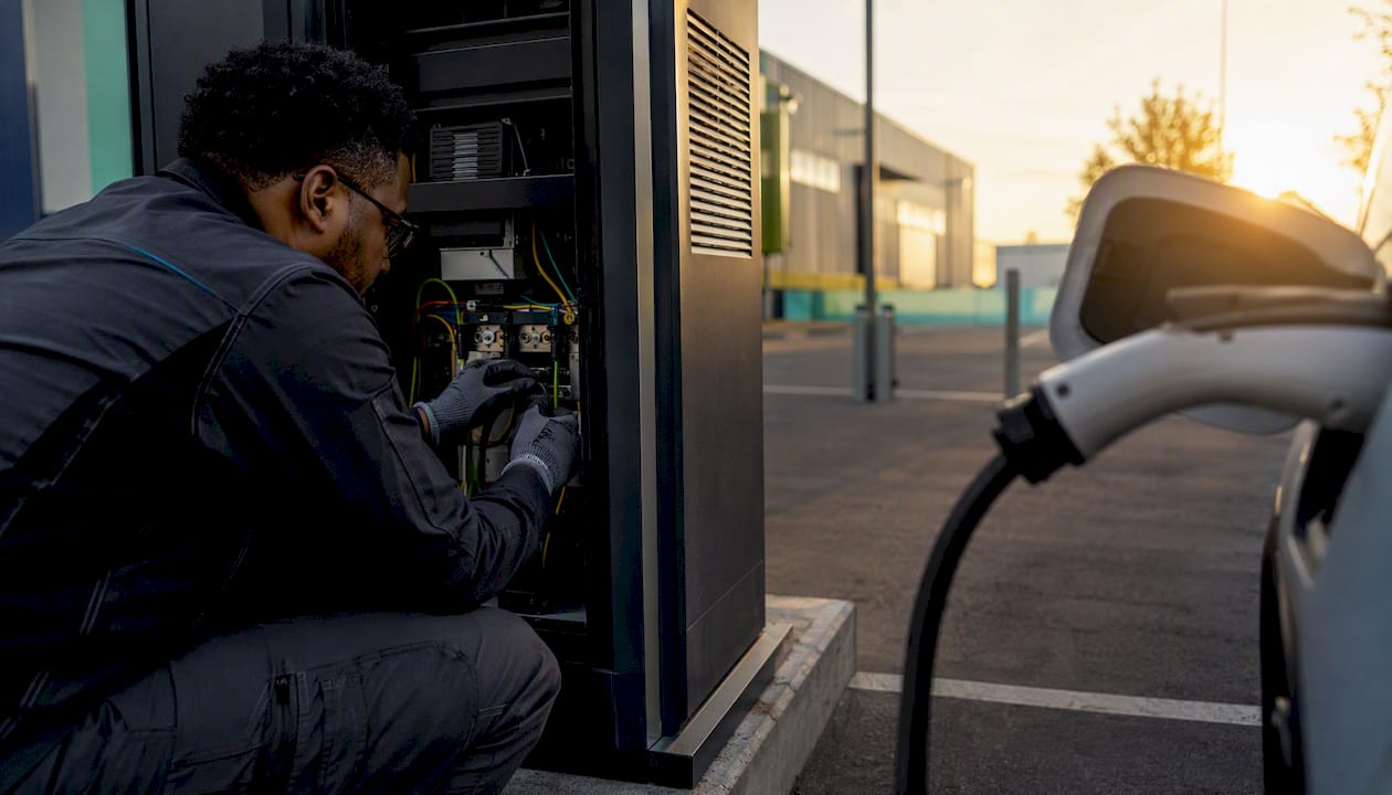
Yes, most outdoor EV chargers on standard PME supplies need PEN fault protection, and there are three compliant ways to provide it. If your chargepoints sit outside on a TN‑C‑S (PME) supply, or export PME earthing to a vehicle, BS 7671 regulation 722.411.4.1 requires protection against an open PEN conductor. You have three compliant routes:
A charger with a verified integrated open-PEN detection device (OPDD), specified to IET 01
A dedicated PME fault detection board serving one or more chargers
A supplementary earth electrode that converts the installation to TT earthing
Every route sits under BS 7671 and IET 01 guidance, and your Distribution Network Operator (DNO) owns the PEN conductor itself. If you ever suspect a live open-PEN fault on the network, call 105 immediately.
Key Takeaways
PEN fault protection is a BS 7671 requirement for most outdoor, PME-fed chargers, and compliance means choosing one of three verified routes and proving it at commissioning.
Point | Details |
Know your trigger | Outdoor chargers on PME (TN‑C‑S) supplies, or units exporting PME earthing, generally need protection under BS 7671. |
Pick the right route | Choose integrated OPDD, a dedicated PME board, or TT conversion based on site layout, ground conditions and charger count. |
Demand real evidence | Insist on IET 01 labelling, manufacturer documentation and independent test evidence rather than accepting claims unchecked. |
Get commissioning right | Require documented earthing readings, functional test results and clear reset behaviour notes at handover. |
Know who to call | The DNO owns PEN conductor faults; report suspected network issues on 105 while you handle protection on your side. |
Work with a specialist | Swift Charging surveys, designs and commissions compliant PEN protection and hands over full documentation for your records. |
Table of Contents
What is PEN fault protection, and why does it matter here?
A PEN conductor combines the neutral and protective earth into a single cable, which is standard practice on PME (Protective Multiple Earthing) supplies across most of the UK. When that conductor breaks somewhere upstream, whether from vehicle damage, corrosion or a dug-up cable, the earth reference for every property fed from that point can rise to a dangerous voltage. On a fixed building installation this is unlikely to cause harm because a person is rarely in direct contact with earthed metalwork and the ground simultaneously. An EV charger changes that picture entirely: a driver standing on wet tarmac, holding a charging connector plugged into a vehicle, creates exactly the contact path that turns a broken PEN into a lethal touch voltage. That is the specific risk PEN protective measures exist to interrupt, and it is why the requirement sits inside BS 7671 rather than being left to general good practice.
Who is responsible for a PEN fault, and when is protection mandatory?
The DNO is legally responsible for the PEN conductor and for repairing a fault on the network side, but the responsibility for protecting people at your chargepoint sits with you as the installation owner. PEN protection is typically required whenever a charger is installed outdoors on a PME (TN‑C‑S) supply, whenever the charger exports PME earthing to a vehicle parked outside, or whenever a chargepoint cannot demonstrate a verified integrated OPDD. Indoor chargers in a properly bonded structure, or installations already run as TT, sit outside the strictest requirement, though a proper site risk assessment should confirm that rather than assume it.
Which protection method actually fits your site?
The three compliant options behave differently once you look past the tick-box compliance question, and the right choice depends heavily on your site.
Integrated OPDD chargers build detection into the unit itself. Manufacturer claims here are only as good as the documentation behind them, which is exactly the gap IET 01 was written to close, standardising how OPDDs behave and how manufacturers must label them. Independent testing gives you a way to check the claim is real: PNDC’s validation of the Easee One confirmed the unit detects open-PEN conditions and isolates its output within the timing sequence BS 7671 expects, which is the kind of evidence you should ask any manufacturer for before accepting an integrated claim at face value.
Dedicated PME/OPDD boards sit ahead of one or several chargers and monitor the supply for the voltage signature of a broken PEN, disconnecting before it becomes dangerous. This is often the more practical choice on multi-charger sites, since one board can protect several units rather than relying on every charger having its own verified detection, and it avoids the groundworks a PME fault detection device would otherwise require in place of digging in an earth electrode.
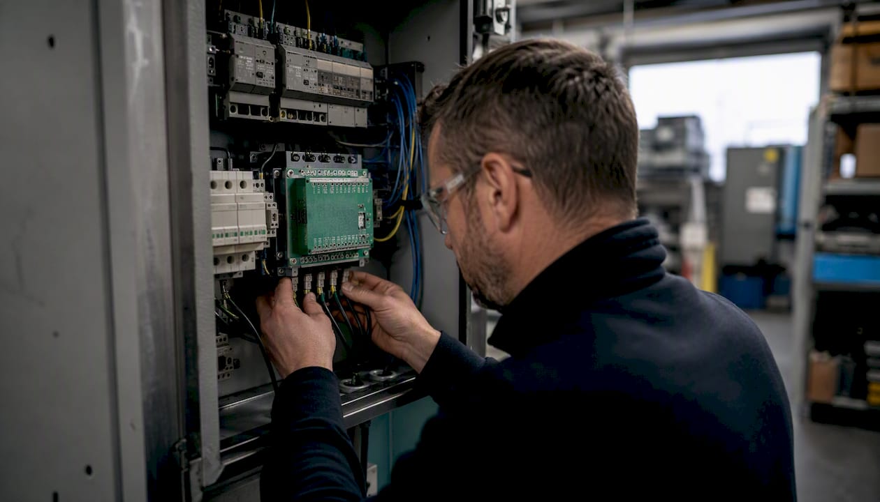
TT conversion via a supplementary earth electrode sidesteps PME earthing altogether by giving the installation its own independent earth. It works well where ground conditions cooperate, but urban and paved sites often make it impractical, and ENA G12/4 guidance on earth resistance and electrode spacing means a designer needs to run proper calculations, not guess.
What happens at commissioning, and what should the paperwork show?
Commissioning is where PEN fault protection either gets proven or gets quietly skipped, and it is the stage most worth scrutinising before you sign off an installation. A compliant handover should include the manufacturer’s specification confirming IET 01 conformance where an integrated OPDD is claimed, plus the actual commissioning test results rather than a generic datasheet.
There is no single simple test that proves open-PEN protection works in every scenario, because the failure mode depends on load patterns and where the break occurs. That is why IET Wiring Matters stresses documented commissioning readings and a proper site risk assessment rather than a tick-box check. Your installer should record earthing resistance values where an electrode is fitted, functional test results for any OPDD or PME board, and clear notes on reset behaviour.
Reset behaviour matters more than it first appears. Many OPDD designs require a manual reset after an open-PEN trip, deliberately preventing automatic reconnection to a supply that might still be faulty. If your handover pack doesn’t say whether the device auto-resets or needs manual intervention, ask before signing off, because that detail determines how your site responds the next time it trips. Labelling to IET 01 should also be visible at the chargepoint itself, not buried in a filing cabinet.
Weighing up the three protection routes
Each compliant method carries a different balance of cost, coverage and ongoing maintenance, and the right one depends on how your site is laid out.
Integrated OPDD chargers are the simplest option for a single unit or small workplace installation, since there’s no separate board to specify or maintain, and the protection travels with the charger. The trade-off is that you’re relying entirely on manufacturer documentation and, ideally, independent test evidence like the PNDC validation, because there’s no visible external device to inspect separately from the charger itself.
Dedicated PME/OPDD boards suit multi-charger sites and fleet depots best, protecting several chargepoints from one point rather than duplicating detection in every unit. They add an extra component to specify and maintain, but for a depot running a dozen chargers, one board is usually cheaper and simpler to manage than insisting every charger has its own verified integrated protection.
TT conversion via an earth electrode avoids PME-related faults entirely and can be the most robust long-term solution where ground conditions allow it. It typically costs more to install, particularly where specialist earthing such as an earth mat is needed instead of a single rod, and it demands proper resistance testing at commissioning and periodically afterwards. On paved courtyards or dense urban sites, it’s often the least practical of the three.
Swift Charging’s view: risk, responsibility and getting the choice right
The DNO owns the PEN conductor and any network-side repair, call 105 if you ever suspect a live fault, but protecting the people using your chargepoints is your responsibility as the site owner. We’d push back on treating this as a single generic spec across a portfolio: soil conditions, legacy switchboards, and whether you’re running one charger or twelve all change the sensible answer. A single-charger workplace install with clean IET 01 documentation is a very different decision from a multi-bay fleet depot on an old switchboard. Trust manufacturer OPDD claims only when the labelling and documentation genuinely back them up.
How Swift Charging gets your PEN protection right, from survey to handover
Getting PEN fault protection right on a live commercial site isn’t a paperwork exercise, it’s a design decision that starts with your ground conditions and supply arrangement, not a generic spec sheet. Swift Charging carries out the site survey and earthing assessment that tells you which of the three compliant routes actually fits your building, then handles the supply design, OPDD or board installation, commissioning and any necessary liaison with your DNO.

At handover, we don’t just leave you with a charger. You get manufacturer documentation showing IET 01 conformance where an integrated OPDD is used, the actual commissioning readings rather than a boilerplate certificate, functional test results, and a plain-English note on reset behaviour so your facilities team knows exactly what happens the next time a fault trips. If you’re planning a new installation, expanding an existing site, or simply want a second opinion on whether your current chargers actually comply, our commercial installation team in Chichester can run a feasibility survey and tell you plainly where you stand.
Sources
Recommended